Wall Thickness

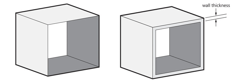
In 3D printing, wall thickness refers to the distance between one surface of your model and the opposite sheer surface. For Aluminum, the minimum wall thickness you can use is 1 mm.
Detail Size

Very small levels of detail (as small as 0.25 mm) are also possible when you print in Aluminum, using Direct Metal Laser Sintering (DMLS). Detail sizes refer to the distance between the surface of your model and the surface of your detail. Letters are also considered as details but they have different specifications (explained further below).
Geometry

Organic or freeform shapes look more attractive in aluminum than angular shapes, right angles, and straight lines. Angles measuring less than 35° tend to lead to poorer surface quality, while steep angles of more than 35° are likely to have better, smoother surfaces. An overhanging structure (e.g. the underside of a table) will be likely to have poor surface quality.
Your model in Aluminum is 3D-printed using DMLS. It is essential to avoid or minimize stress while printing your model, as it might eventually deform the model. We advise you to round off or fillet the edges in your design. Also, avoid sharp edges for the same reason.
The ideal shape to make when using DMLS is that of a mesh. These shapes are easy to design for this process and deliver the best results.
Dimensional Accuracy

DMLS is the metal 3D printing process with the highest dimensional accuracy by far. Dimensional accuracy doesn’t relate to the detail of your model but to its deviation from the nominal size. The general tolerance of the material we offer is 2%, with a minimum of ±200µ. Normally, the general tolerance for 3D printed Aluminum is 0.2%. However, for typical use, we have chosen an optimal balance between affordability and accuracy.
Support

Aluminum is 3D printed using DMLS. Direct Metal Laser Sintering begins with a bed of aluminum powder, which is then sintered by a laser. Support structures are also 3D printed in aluminum. The support structures keep your model rigid during printing and prevent internal stress and deformations. Walls or overhangs with angles measuring below 40° typically need to be supported as they would otherwise collapse during the printing process. Afterward, the support is removed manually and your part is sandblasted. Some evidence of the removed support structures may still be visible.
Powder Removal

Models can be hollowed out. Try to use a minimum wall thickness of 1 mm and foresee a minimum opening of 3 mm in diameter. This opening will serve as an exit for the extra, internal powder. Larger and complex cavities need multiple holes and an increased size. We recommend a minimum diameter of 7 mm. Holes in the center of your model are usually the best as they allow most of the powder to be removed.
Holes and Threaded Holes

The minimum recommended diameter for a hole is 1 mm. This is the minimal diameter needed to remove internal powder; if the hole is smaller the powder will get stuck inside the geometry. Complex and irregularly shaped holes or interior spaces are impossible for us to inspect or remove the powder from completely. Therefore, we cannot guarantee that these designs will come out of the printer looking exactly like their design. If perfectly straight holes are required, expect the holes in your model to be slightly smaller than designed. You can drill out the hole to match your exact measurement once the part has been built.
Although dimensional accuracy is high, threads cannot be made of this material. If your design requires threaded holes, we recommend making slightly smaller holes in your 3D design file and drilling and cutting out a thread into the holes of the 3D printed part. Small adjustments to the final printed model can be made using traditional mechanical methods.
Nested Objects, Hinged and Interlinking Parts

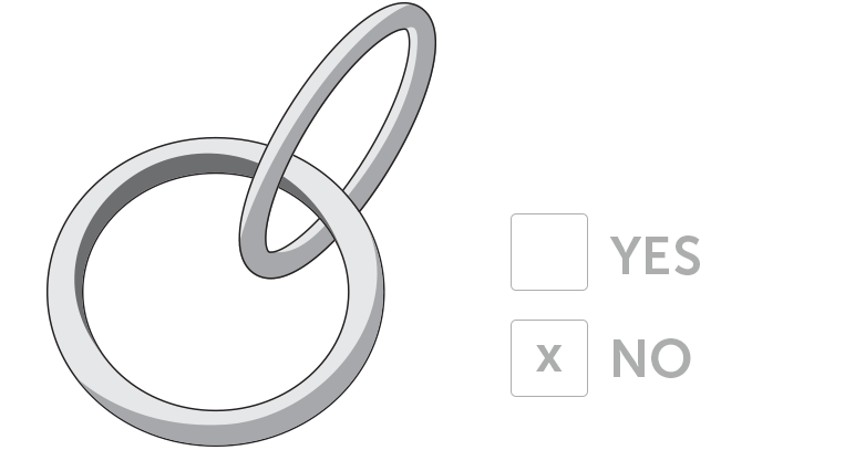
Nested objects (objects floating within another object), hinged parts, and interlinking parts such as chains cannot be made using DMLS because this technology requires the use of support structures.
Engraved Text and Surface Details

For engraved text or surface details, we recommend letters with a minimum line thickness of 1 mm, a minimum overall height of 5 mm, and a minimum depth of 0.5 mm. For embossed text or surface details, we recommend letters to have a line thickness of at least 1 mm, an overall height of at least 5 mm, and a depth of at least 0.5 mm.


