General Guidelines
Wall Thickness
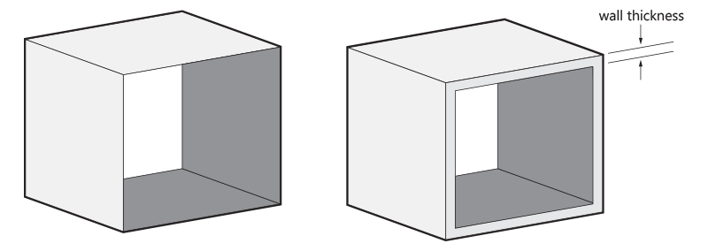
In general, we recommend a wall thickness of at least 1 mm. Large parts may require larger wall thicknesses or added ribs or fillets for reinforcement.
For the Extra Smooth finish, we recommend a minimum of 2 mm. Please check all details by clicking on guidelines for extra smooth models in the menu on the left.
Please note that the Rubber-like material has a hardness of Shore A 90, which means it is a hard material on the Shore A hardness scale. To get a flexible design, it is advised to keep the walls below 5 mm. In general thinner walls will be more flexible and thicker walls will result in less flexible and harder sections.
Hollowing & Holes
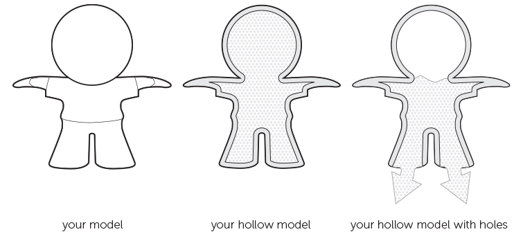
We advise hollowing out a solid model as much as possible, and when the wall thickness exceeds 20 mm. We recommend a wall thickness of 1-2 mm and the inclusion of at least two holes with a minimum diameter of 10 mm for powder removal.
It is possible to create holes or perforations and ducts. The recommended minimum diameter size of these holes is 2 mm but some post-production will be needed to remove excess powder. Some residual powder may be stuck on the inside of complex ducts. It is advised to design a strip or chain through the duct to help in dislodging the powder once the part has been printed. In general, complex holes or ducts require larger diameters in order to achieve thorough removal of the unfused powder.
Lattice Structures
Interlocking Parts
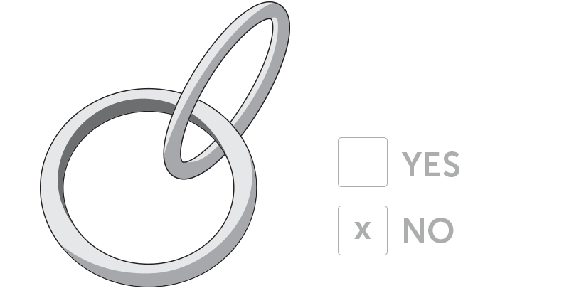
It is possible to print interlocking parts and assemblies in a single build. Parts that are printed together should have a minimum clearance of 0.5 mm.
Embossed and Engraved Details
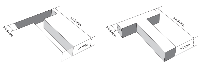
For embossed or engraved textures, we advise a minimum thickness of 0.25 mm. For legible engraved or embossed text, we recommend letters with a minimum line thickness of 0.5 mm, a depth of 1 mm, and an overall height of at least 2.5 mm.
Guidelines for Grouped Models
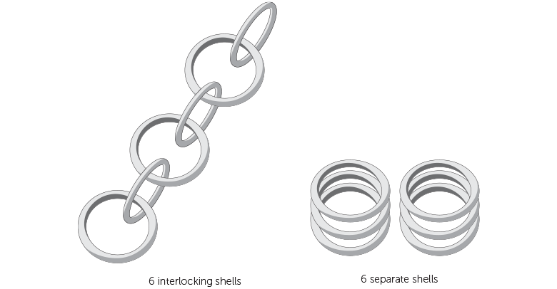
It’s possible to have several individual shells within a single 3D file. If the shells are part of interlocking elements, such as chainmail, for example, consult the rules indicated in the “The Right Space Between Your (Moving) Parts” a paragraph earlier. If the shells in your design are not interlocking or intersecting, additional design rules and considerations can be found below.
O Part, Where Art Thou?
Connecting Parts
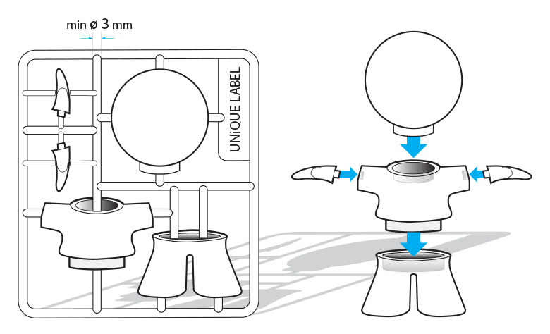
One way of making sure all the shells in your design stay together and can be processed as one part is to connect the different shells with support beams. It is important that the parts are well connected and that the connection beams are strong enough. Use a minimum wall thickness of 3 mm as anything thinner will not be strong enough to support the different parts of your design.
The heavier/bulkier your individual parts are, the thicker the connecting beams should be. If the connections between the parts are too weak, there is a risk that your parts might get lost. You can prevent bulkier shells by hollowing them out. Just don’t forget to provide several large drainage holes so that the powder on the inside can be removed – otherwise, your part will not become lighter. The part’s wall should be less than 5 mm thick.
It’s also advisable to have 4 firm connections per shell. The larger the shells, the more difficult they are to connect properly. That’s why the sum of the dimensions of the imaginary box (X+Y+Z) around your design should be less than 350 mm.
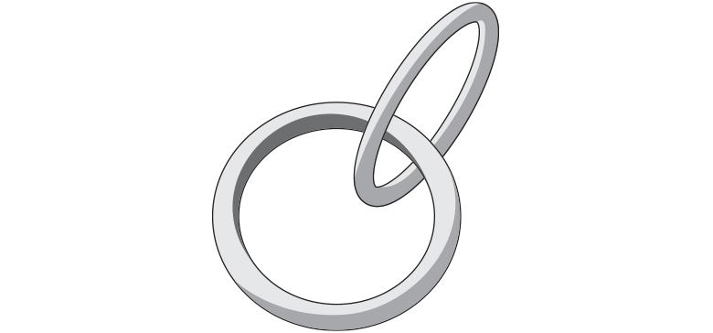
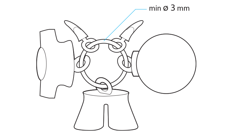
Combining Parts on a Ring
Outcomes
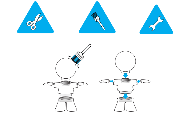
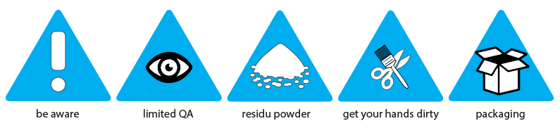
Once printed, each model will need to be cleaned with a brush and sandblasted to remove the excess powder stuck to your model. This is the same for grouped models but in these cases, access to all of the parts is more difficult. Please be aware that some residual powder might be present when receiving your parts. To clean your parts further, the residual powder can be removed with a brush or compressed air.
Please be aware that grouped models are only offered in natural finish. Because of the limitations stated above for these types of files, a good result cannot be guaranteed. Other finishes can be achieved through various post-processing techniques but will require perfectly cleaned and fully accessible parts, which is not possible for grouped models enclosed in a container immediately upon printing.
DISCLAIMER
Guidelines for Extra Smooth Models
For this finish, your model is put into a chamber with a solvent that seals the surface by removing the porosity and change the grey color to black.
Pending post processing
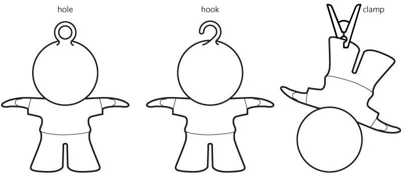
Due to nature of this post processing technique, your part will need to be suspended during this step. If your design has holes with a diameter above 1.5mm or hooks, we will use these for hanging. Large parts will require more suspension points than small parts due to their weight. If there are no holes or hooks foreseen, we will use metal wire or clamps to hang your part in the processing chamber.
Please be aware that these touch points will always leave a small marks on the model as these points will not be smoothed.
Wall thickness
The Extra Smooth finish is the result of an automated chemical smoothing process, which uses a solvent to seal the surface of the part by removing porosity. As the solvent reacts and is receptive to material, the best result can be achieved with bulky parts with homogenous wall thicknesses.
We recommend walls above 2 mm for the best result. Walls of 1 mm or below are less optimal as they will be smoothed less and have a higher chance of getting deformed during the process. Parts with a significant variation in wall thickness are likely to appear to be smoothed in an uneven way. So homogeneous wall thicknesses are recommended.
For the same reason, we strongly recommend filleting (rounding off) or chamfering perpendicular and sharp corners to ensure a homogeneous result. The larger the radius, the softer the transition will be as well as the outcome.
For surface details, we recommended embossing over engraving for the same reason.
Interlocking parts
Variations & Accuracy
As the process is dependent on a lot of different aspects like orientation of the part, position in the smoothing chamber, other geometries in the chamber, etc some variations can be expected in smoothness especially for cavities, the inside of tubes and internal channels and as well as in color.
As the post processing technology is still in its trial phase, we cannot guarantee an accuracy similar to the natural finish which you would typically expect. The manufacturer of the smoothing process indicates a general accuracy level of ±0.4%. From our experience we see that the accuracy is highly geometry dependent and cannot assure the manufacturer's accuracy claim. For this reason, we do not ensure a perfect fit for matching or mating parts.
Design Specifications
±0.9%(XY) up to ±1.8% (Z) with lower limits on ±1 mm (XY) up to ±1.5mm (Z)
- 274 x 370 x 380 mm (Natural)
- 150 x 150 x 150 mm (Black dye)
- 256 x 340 x 360 mm (Extra Smooth)