General Guidelines
Wall Thickness
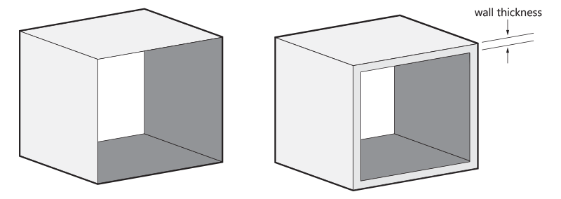
Hollowing
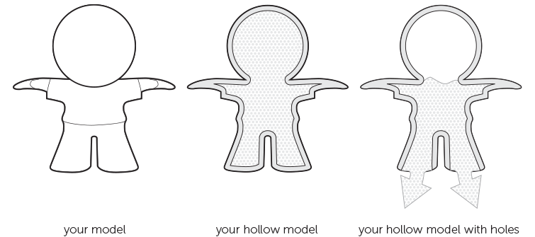
If possible, try to hollow out your part. This avoids deformation and discoloration during the printing process. You can either hollow out your part without a surface hole, which means that unsintered powder will remain trapped inside, or you can design a strategically placed hole (two would be even better) so that the unsintered powder can be easily removed after printing. If the part needs to be reclosed, design a lid with a diameter allowing for 0.5 mm play between the part and the lid.
If your part has walls thicker than 5 mm, our production team may hollow out the part to prevent deformation and discoloration. For parts with wall thickness higher than 10 mm wall thickness, this is done by default. In that case, the powder will stay trapped inside.
Holes and Channels
Holes with a small diameter are exposed to a lot of heat during the sintering process. This can cause the powder inside the holes to become fused. To make sure that holes in your parts remain clear, design a diameter of at least 1 mm.
Longer internal channels can be difficult to clear out, especially if the powder is partially sintered together. We recommend a diameter of at least 3 mm for internal channels.
Warpage and Deformities
Interlocking or Moving Parts
Assembly
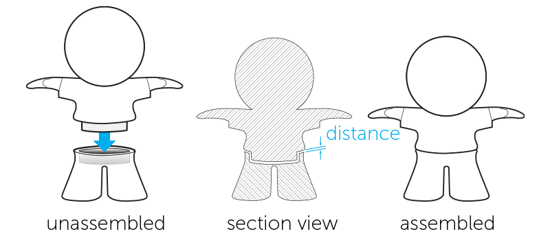
When designing parts that need to be assembled, it’s important to maintain enough distance between the parts. A perfect fit in your CAD software does not necessarily ensure a perfect fit after printing because your software ignores the friction present in the real world. Therefore, always leave at least 0.6 mm between the different parts. For parts with large surfaces and wall thicknesses, you will need to maintain even more distance between the parts.
In order to help us print your parts with the best possible dimensions for assembly, please design your files with an orientation equal to the relative orientation of your parts in the final assembly.
Embossed and Engraved Details
Guidelines for Grouped Models
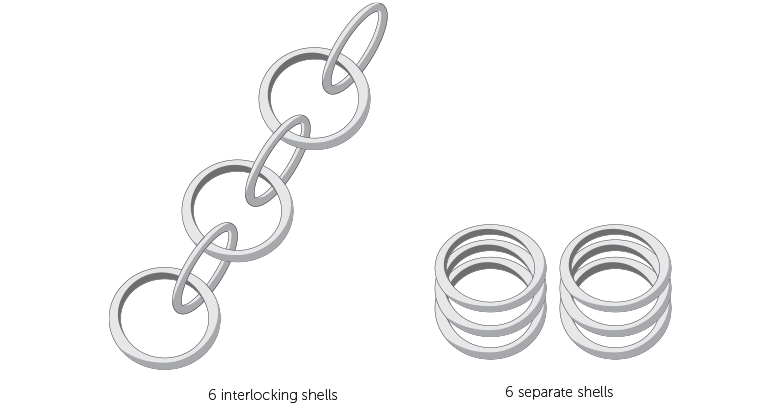
It’s possible to have several individual shells within a single 3D file. If the shells are part of interlocking elements, such as chainmail, for example, consult the rules indicated in the “The Right Space Between Your (Moving) Parts” a paragraph earlier. If the shells in your design are not interlocking or intersecting, additional design rules and considerations can be found below.
O Part, Where Art Thou?
If a single file contains several shells that are not connected or interlocking, this can cause considerable challenges for our production team. First, identification of all your parts or shells may be challenging. When producing your design, your parts are combined with parts from other orders in the 3D printer. Most printers have a fixed printing volume. To save time and costs, we fill up the machine with as many ordered parts as the build will allow. This virtual 3D layout is then used for printing. Once the printing process is finished, we end up with a block of powder with all the different parts inside. If you have uploaded multiple small, unconnected shells, you can see how it could be very difficult to go back and recognize all the different shells contained within the powder block. Therefore, to solve this issue, we only accept models that are either connected or that can be enclosed in a container or box. Continue reading below for more details and some important consequences of these options.
Connecting Parts
One way of making sure all the shells in your design stay together and can be processed as one part is to connect the different shells with support beams. It is important that the parts are well connected and that the connection beams are strong enough. Use a minimum wall thickness of 3 mm as anything thinner will not be strong enough to support the different parts of your design.
The heavier/bulkier your individual parts are, the thicker the connecting beams should be. If the connections between the parts are too weak, there is a risk that your parts might get lost. You can prevent bulkier shells by hollowing them out. Just don’t forget to provide several large drainage holes so that the powder on the inside can be removed – otherwise, your part will not become lighter. The part’s wall should be less than 5 mm thick.
It’s also advisable to have 4 firm connections per shell. The larger the shells, the more difficult they are to connect properly. That’s why the sum of the dimensions of the imaginary box (X+Y+Z) around your design should be less than 350 mm.
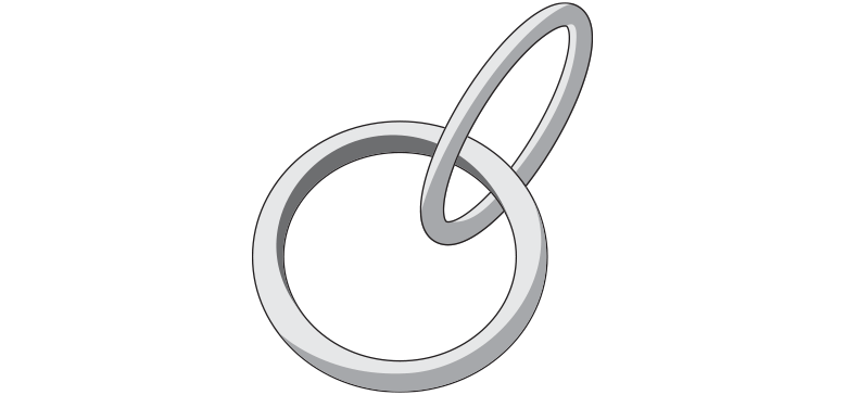
Combining Parts on a Ring
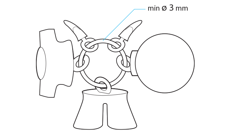
If your parts have holes through them, another way to keep them connected is by combining them on a ring. Putting your parts on a key-chain style loop ensures that we can process your designs as one part. However, when grouping your parts with this method, we can no longer orient them individually or define the correct space between them. So to avoid any problems during the build, prepare your design with a minimum of 1 mm spacing between each part. The minimum thickness of the connecting loop should be 3 mm. Make sure to limit the number of parts on the loop as too many items or large and heavy parts will have a greater chance of causing the loop to break. Designs, where the chance of breakage is too high, will not be allowed.
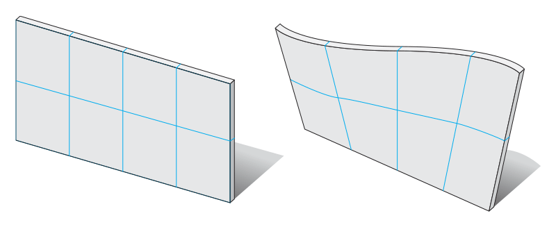
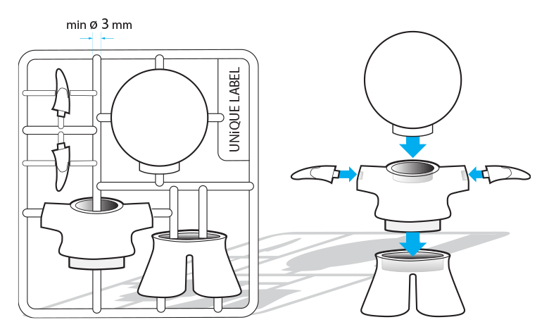
Grid Container
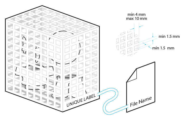
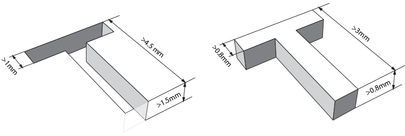
Another option that will allow you to have multiple shells printed in one go is to place all of your parts into a container. This means that you will need to design a container around you parts. Here are some basic things to take into account when designing that container. Always engrave your container with a unique label identical to the filename of your design so we can easily identify your box as we won’t be able to check the contents of your container. Use a clearly readable font such as Arial Black for the engraved text. We recommend using letters with a minimum line thickness of 1 mm, a depth of 0.8 mm, and an overall height of at least 3 mm.
It is advised to use a perforated container because that will allow us to remove most of the excessive powder from your parts. We recommend the following minimum feature sizes for your container: at least a 1.5 mm thickness for the grid lines; and a minimum of a 4 x 4 mm square up to a maximum of 10 x 10 mm. Make sure the parts on the inside of your container cannot pass through the perforations of the container to ensure that all your parts stay together. Parts that pass through the holes might get lost.
In addition to your container features, you also need to keep a minimum spacing distance of 3 mm between each individual part and between the sides of the container and the parts. If the distance is smaller than this, parts might get sintered together.
If the overall volume of your container is larger than 1700 cm³, you should limit the density in the container because parts that are too dense can cause an irregular cooling down process. This may cause yellowing and deformation of your parts. Limit the total volume of the model to 10% of the overall volume of the container.
If you have fragile parts in the container, we recommend connecting the individual parts to the container. This will prevent fragile parts from hitting each other during shipment. Otherwise, your parts will be loose in the closed container and may damage each other by moving around during the shipping process.
Outcomes
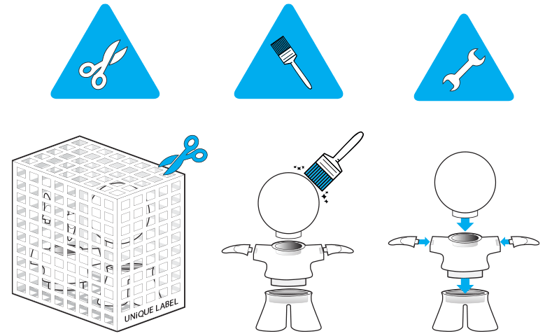
Once printed, each model will need to be cleaned with a brush and sandblasted to remove the excess powder stuck to your model. This is the same for grouped models but in these cases, access to all of the parts is more difficult. Because parts will be connected to each other as well as a container, this may prevent every edge and corner from getting sandblasted. Please be aware that some residual powder might be present when receiving your parts. To clean your parts further, the residual powder can be removed with a brush or compressed air.
Please be aware that grouped models are only offered in natural finish. Because of the limitations stated above for these types of files, a good result cannot be guaranteed. Other finishes can be achieved through various post-processing techniques but will require perfectly cleaned and fully accessible parts, which is not possible for grouped models enclosed in a container immediately upon printing.
DISCLAIMER

The techniques for combining multiple parts into one file that are described above will not allow us to make accurate quality inspections, to provide optimal cleaning of each part by our production team nor to pack and protect each individual part in the best way for shipment. Grouped models are only offered in natural finish. Choosing these options implies that you accept these conditions and don’t mind getting your hands dirty to do some extra cleaning of your parts.