General Guidelines
Wall Thickness

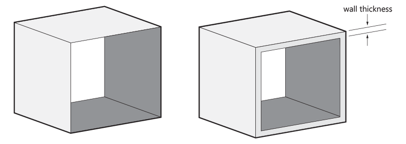
In general, we recommend a wall thickness of at least 1 mm. Large parts may require larger wall thicknesses or added ribs or fillets for reinforcement. It is possible to have thinner features with walls of only 0.5 mm for living hinges, but here the length needs to be limited to 10 mm when they are only attached at one end or 25 mm when attached from two sides. Although hinges can be positioned differently without the risk of breaking (thanks to the isotropic mechanical characteristics of the material), it is advisable to avoid making the thinnest sections of your living hinges parallel to the Z plane.
Hollow models & holes

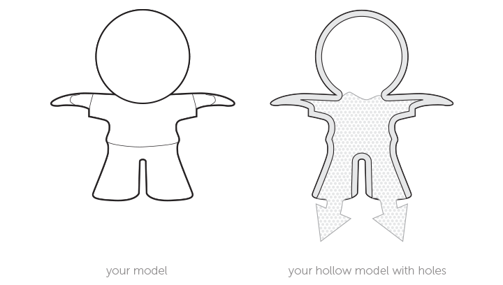
We advise hollowing out a solid model as much as possible, and when the wall thickness exceeds 20 mm. This will save material and prevent sink marks. We recommend a wall thickness of 2-3 mm and the inclusion of at least two holes with a minimum diameter of 2 mm for powder removal.
It is possible to create holes or perforations and ducts. The recommended diameter size of these holes is 2 mm, with a minimum of 1 mm, but some post-production will be needed to remove excess powder. Some residual powder may be stuck on the inside of complex ducts. It is advised to design a strip or chain through the duct to help in dislodging the powder once the part has been printed. In general, complex holes or ducts require larger diameters in order to achieve thorough removal of the unfused powder.
Interlocking parts

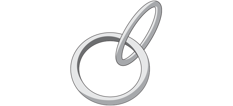
It is possible to print interlocking parts and assemblies in a single build. Parts that are printed together should have a minimum clearance of 0.5 mm.
Engraved Text and Surface Details

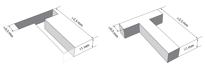
For embossed or engraved textures, we advise a minimum thickness of 0.25 mm. For legible engraved or embossed text, we recommend letters with a minimum line thickness of 0.5 mm, a depth of 1 mm, and an overall height of at least 2.5 mm.
Big Flat Planes Can Cause Warping

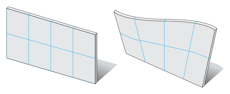
We strongly recommend that you do not design large, flat plains in dimensions like an A4 page. In most cases, your model will deform. This process is called “warping”. Even if you create support ribs under your plane, it doesn’t solve the problem. It increases the chance of deformation even more. The key here is to avoid big flat planes.
