Tutorial: 3D Printing with Strata Design 3D
Strata Design 3D is a 3D modeling software that is renowned for being easy to use by every day designers while providing professional quality and photoreal results. What many don’t know is that Design 3D is also a great product for 3D printing. Take a look at this tutorial in order to learn how to prepare your model for 3D printing and to realize your vision both in the virtual and physical worlds.
About Strata Design 3D and the Author
If you don’t already own a copy of Design 3D you can get a free trial version of the software here. During the month of July 2015, as part of a special joint offer between Strata and i.materialise, you can use this coupon code: MAT3D to get 35% off of any purchase on the Strata store.
This tutorial is written by expert Strata user Chris Tyler. With hundreds of tutorials to his credit, this project is a continuation of his Plastic Pill Bottle tutorial series, where Chris shows you how to build this model. In the tutorial below Chris discusses techniques for 3D printing. Though applied specifically to the pill bottle project, the general principles can be applied to any model in Strata Design 3D.
The Movie Version
If you’re like me, you’d rather watch this tutorial than read it – so we provided both versions! Below are two videos covering all of the details of this tutorial. Below that is the tutorial in written form. Both the written and video tutorials are by Chris Tyler and assume a base level of understanding of Strata Design 3D CX 8:
The Beginning Basics
In order to correctly print a 3D object various factors have to be taken into account and correctly implemented. For 3D rendering some of these factors aren’t very important, such as having a fully closed “manifold” object (often referred to as water tight), or even having the model be set to the physical size, but for 3D printing there are certain issues you do need to watch for:
- Object is set to physical size
- Closed ‘water tight’ or manifold meshes
- Thick walls (not paper-thin)
- Overlapping/intersecting geometry
- Proper final resolution (surface refinement)
The Example Project
For this tutorial the object that will be prepared to be printed is a variant of a common pill bottle object. The targeted printing system for the tutorial is the i.materialise online printing service. This service provides an extensive list of options and materials that may make it a superior choice over owning your own printer – however, the principles discussed in this tutorial apply to any 3D printing project.
The pill bottle project was originally developed for a design study and for high quality renderings, and so parts of the object weren’t modeled since they wouldn’t be visible, such as the inside (the wall thickness) and the bottom of the mesh.
The object type is a polygon mesh that was designed to then be used to produce a subdivision surface object. Subdivision surface objects are ideal for 3D printing because the resolution of the final mesh can be adjusted for different purposes. The resolution needed for rendering may not be quite high enough for 3D printing and the subdivision process allows for an easy ‘up-resing’ of the geometry.
So, there are a few steps that need to be followed so this object can be ready to be 3D printed:
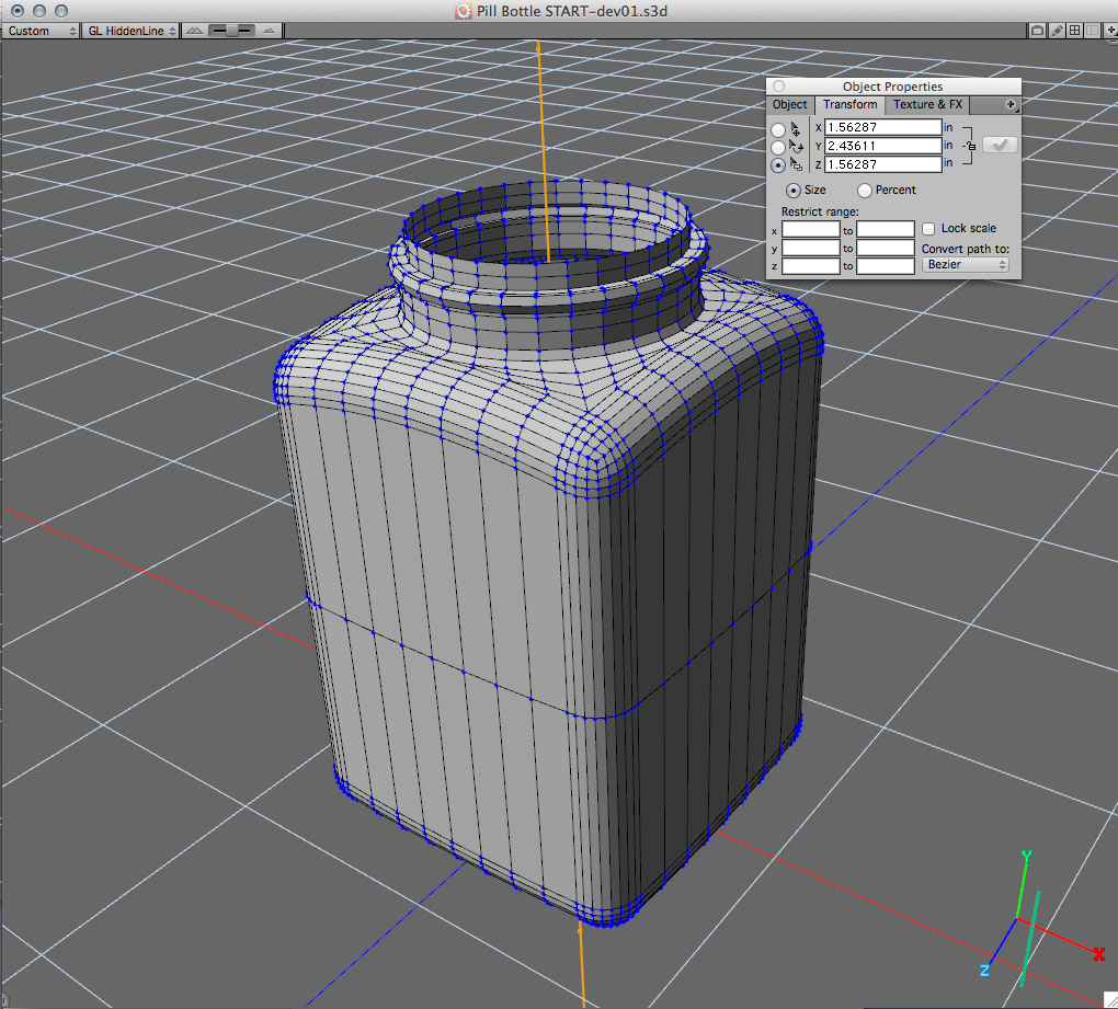
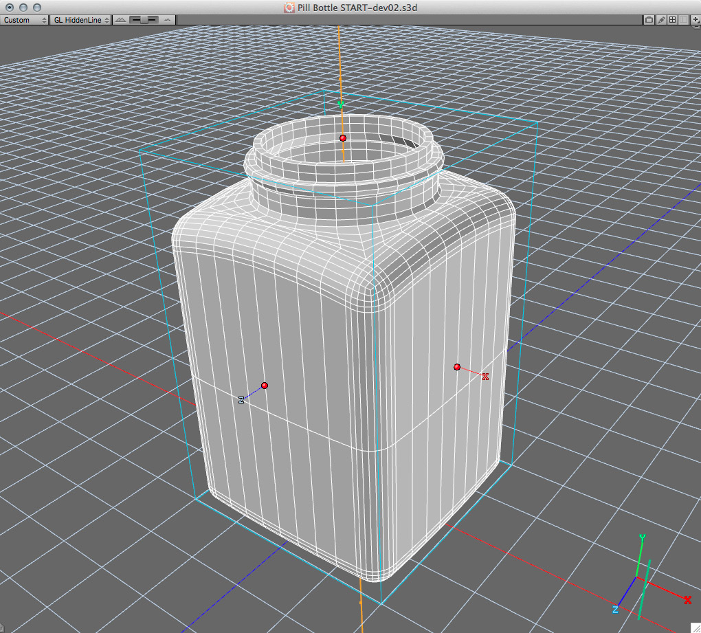
Step 1: Check Physical Size
The size of the printed object needs to be determined. It’s quite common for 3D objects to be modeled or sized to non-physical dimensions, or it may be that the object was modeled to the correct size, but the 3D print is going to be a miniaturized version (say at 1/10th size). Moving from the virtual world, where you can be a bit more fast-and-loose with reality, 3D printing requires explicit definitions of your models.
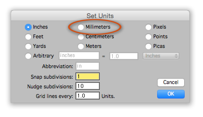
So the first thing to do is ensure the object is the correct physical size either for the purpose of scaling to a particular factor (i.e., 10% of original) or so that at 100% the correct size is printed. For convenience, Design 3D’s Publish 3D Content function has a scaling option for those situations where scaling is desired. The i.materialise system references printable sizes in millimeters. In order to determine your size in millimeters, change the Units to Millimeters (menu command View > Set Units)
Step 2. Close Open Areas
Make sure the object is ‘water tight’, that is, closed. Technically this means there can’t be any holes in the mesh, which could mean obvious open area such as the bottom or top of the container, or it may mean apparently closed areas which nonetheless have unwelded vertices (overlapping but not welded). Design 3D has a function that can look for these areas, called the Select Non-Manifold function, located within the polygon modeler using the context menu (right-click on the object surface).
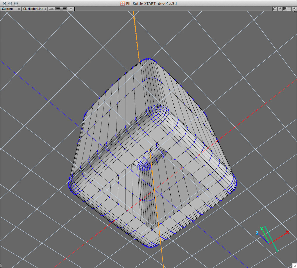
The bottom has an obvious open area that needs to be closed. It wasn’t necessary for doing 3D renderings and so wasn’t modeled. I closed it by selecting the open perimeter and creating a single polygon using the Fill function. I then cut that out and pasted it to a new object. Once I removed the perimeter points, leaving the 4 corner points, I ran it through the Smooth Mesh function and diced it up into a 6×6 mesh. Then I copied it back into the container mesh and did a tolerance weld with a wide tolerance to make sure all the points were welded.
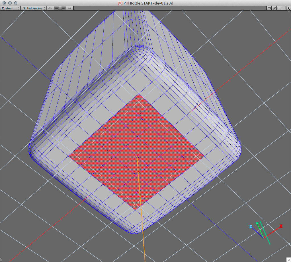
The bottom hole is now closed.
Then, in edge mode, I selected the Select Non-Manifold function to look for any areas that are either open or are not correctly welded. In Edge selection mode and Hidden Line view mode I was able to see where the areas that need attention are (you can also use the Fits to Selection command from the Views menu) . The top area obviously is open, but down the sides are some edges which are overlapping but not welded. During the modeling process these didn’t get properly welded and they need to get fixed.
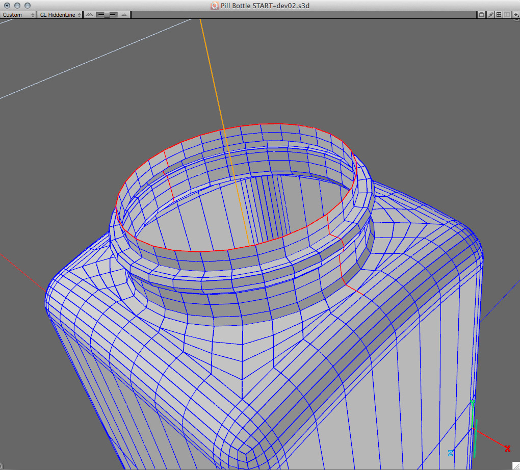
Open areas, both obvious and not so obvious. If these aren’t corrected the object will fail to print.
To correct the overlapping but non-welded edges, I switched to Vertex mode and invoked the Tolerance Weld function with a somewhat wide tolerance range to make sure those vertices were welded.
Step 3: Add Thickness / Look for Overlap
The 3D printing process requires a closed volume, while 3D rendering software does not. In this case the container wasn’t modeled with thickness, even though a real physical object would have walls with thickness. Design 3D has a thickness function, but I decided to do it manually because I wanted to control an area that could possibly produce overlapped geometry.
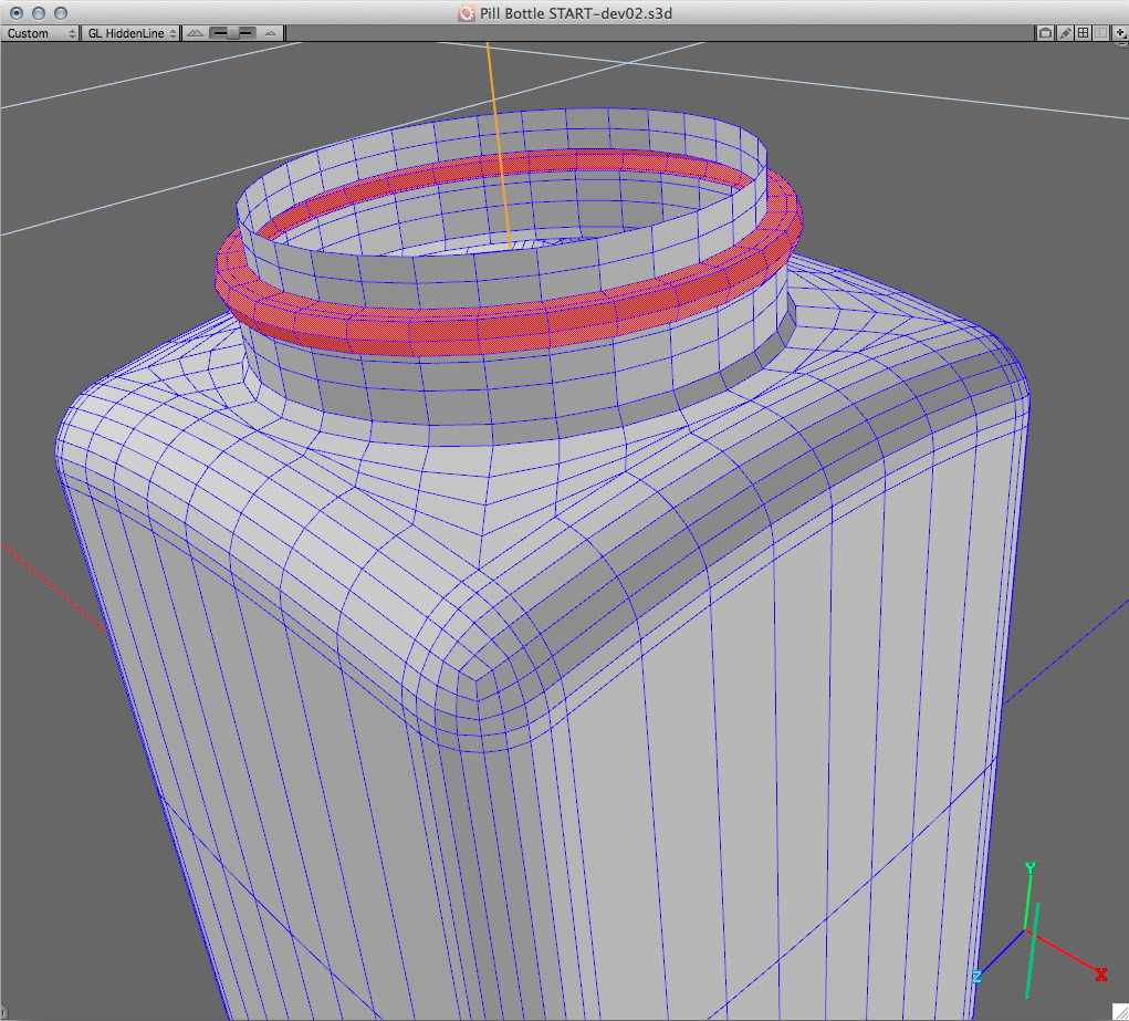
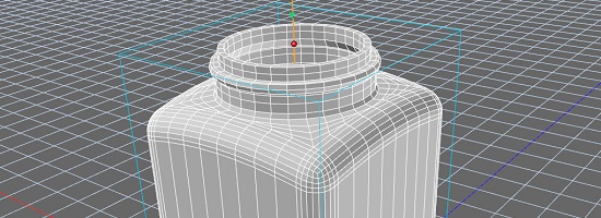
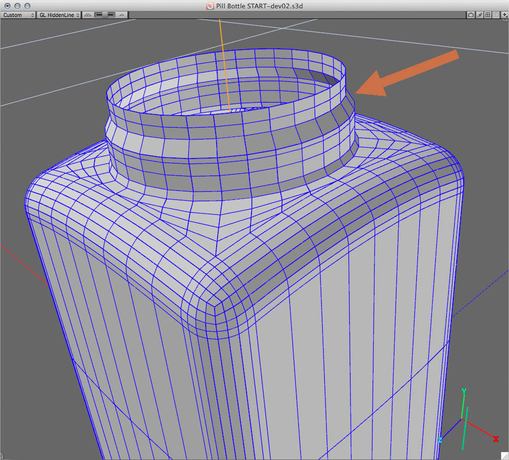
The selected ring of polygons will intersect when inwardly extruded.
The top selected ring around the neck will produce some overlapped polygons when thickened procedurally and this would fail to print. We would have to adjust the overlapped/intersecting geometry which would be a bit of a pain, so for this reason I will produce thickness manually.
The current geometry is the outward facing wall, so we’ll be extruding inward.
I copied all the geometry, with the exception of the selected ring as shown above. I pasted this to its own object (in Object mode, not inside the polygon modeling environment), and then connected the missing ring section where the protruding ring geometry was.
Deleted ring (on a duplicate set of geometry), then bridge to close the gap.
In order to add thickness, we need to know what the minimum thickness for a given i.materialise material. In this case we’re going to use the default polyamide material which has a minimum thickness of about 1 millimeter.
In Face mode, I selected all the polygons and double-clicked the Move tool in order to set the Nudge value to 1mm. I then used the Extrude Normal tool, and pressed the down arrow key to extrude inwards one nudge step – which is now 1mm.
Inwardly extruded geometry by 1mm.
At this point it’s important to look over the geometry to make sure there is no overlapped/ intersecting geometry as a result of the extrusion.
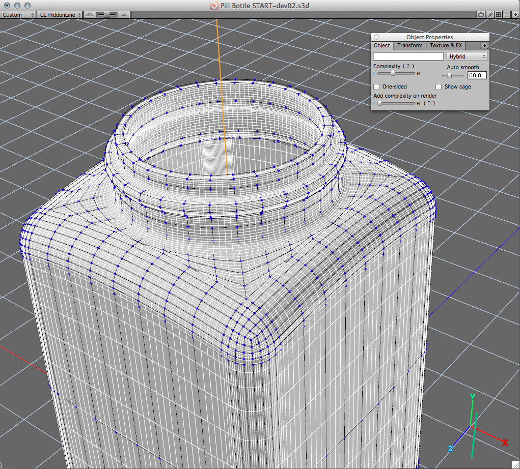
The geometry looks good, and so I merged the outside geometry back with the inward ‘thickened’ geometry. I selected both objects, grouped them, and ran them through the Convert function in order to weld them into a single polygon mesh. At this point it would be good to examine the mesh again within the polygon modeler, running the Select Non-Manifold function to make sure no overlapped and unwelded geometry is present. I finally ran the Unify function to ensure all the normals were facing in the correct, outward direction.
This object now has thickness and is closed.
Step 4: Set Final Resolution
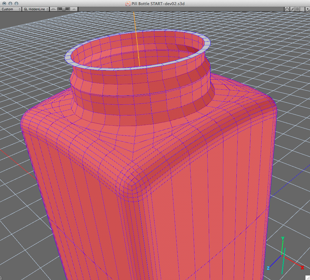
Now that the geometry is finalized, I turned on Subdivision surfaces for bottle geometry. The default is level 2 subdivision which for this object is good. Design 3D will automatically send the subdivision geometry to i.materialise, not the polygon cage. A level of 3 would also probably work but i.materialise warns against producing meshes with too much resolution – more isn’t necessarily better.
Subdivided mesh.
Step 5: Send the Geometry to i.materialise
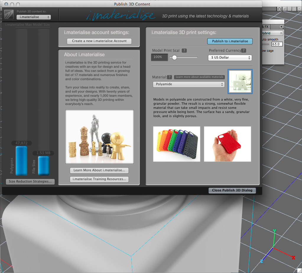
Now that the geometry is finalized and with the object selected I want to send it to i.materialise to test whether it passes various checks which are performed by their analysis software. So I invoke the Publish 3D function, and then select i.materialise. In the Publish 3D dialog, pressing the ‘Send to i.materialise’ button doesn’t actually invoke the final 3D printing process but instead conveniently sends the data to the i.materialise website, along with preferred material type and currency. These options can still be changed in the i.materialise website, so there are several levels where choices can be made even after you’ve sent the data.
I’ve selected polyamide (go here for a full discussion about requirements for this material) and then clicked the Publish button. The subdivided mesh is sent to i.materialise and it is examined to make sure there are no problems. It will then take you to the i.materialise website and show you the instant price for a professional 3D print.
Check out the Strata website in order to find out more about the Design 3D software and don’t forget to use the promo code ‘MAT3D’ to get 35% off of any purchase on the Strata store throughout July 2015.
If you want to learn more wall thickness and file resolution for 3D printing we have the right tutorials for you on our blog. You should also take a look at our “5 Mistakes to Avoid When Designing a 3D Model for 3D Printing” blog post.